Vitap "The Innovators of the Industry"
CLICK HERE FOR BROCHURE
MACHINE SPECIFICATIONS
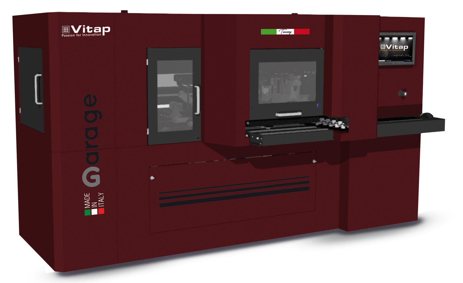
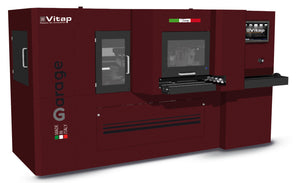
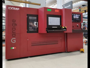
GARAGE CNC Machining Center
Vitap uses 3-dimensional solid modeling systems to design its working centers which are built with a mobile carriage and stationary basement. The carriage moves in a longitudinal direction with respect to the basement (y axis) and supports a pair of carriages which determine the movement of the Z axes. The X and Y axes define a plane parallel to the floor and the Z axis moves up and down perpendicular to this plane. This configuration allows a remarkable reduction in the machine’s overall size and improves the machine’s performance and functionality. The basement and the beam are made of electrically welded steel and are ribbed and strengthened internally to guarantee maximum rigidity even under intense working. The structures undergo a thermally-controlled normalization cycle.
QUALITY CONTROL
All phases of assembly undergo conformity checks according to special testing procedures. The alignment of all the linear guides is carried out using an electronic level guaranteeing straightness and parallelism tolerances to be within 0.02 mm per linear meter. On all machines, positioning precision and bi-directional repeatability of the axes is checked using an interferometer laser system. Bi-directional positioning precision is guaranteed within a tolerance of ±0.05 mm. An electrical test of the whole system is carried out on each machine according to CEI EN 60204-1 legislation.
LINEAR MOTION SYSTEMS
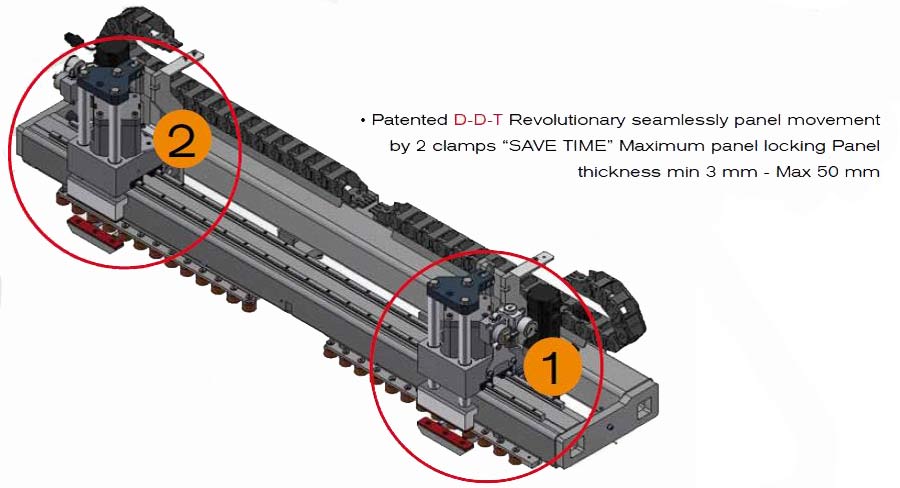
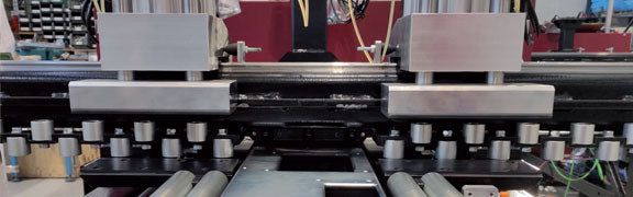
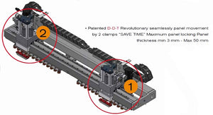
The X axis movement is obtained through the use of the patented DDT or Double Dynamic Transport system. The system is composed of a two gripper system which are driven by two brushless motors. By using two grippers, material can be seamlessly and continuously moved along the X axis without interrupting the milling or channeling processes. The system also provides considerable stability of the piece as it is being milled. The use of a single clamp is also used in the case of a smaller piece where the use of both grippers is not feasible. The Movement of the grippers in the X and the carriage in the Y axis are by brushless motors driving eplcyclic reduction gear, rack and pinion with a high degree of precision. The mobile beam or carriage moves on high precision pre-loaded ball runner blocks and linear guides made of rectified and hardened steel. Ball runner blocks for all axis are equipped with a seal guaranteeing maximum protection from dirt and dust.
Z AXIS - The carriage for this axis is made from an aluminum alloy with highly rigid mechanical properties. Movement of the axis is by ball nut with pre-loaded lead screw in order to guarantee high speeds with minimal wear. The carriage is mounted on pre-loaded ball runner blocks which slide on very high precision linear guides made of rectified and hardened steel. Z axis motor and ball screws are sized to avoid the need for pneumatic assistance. All axes are driven by AC brushless motor fed and controlled by digital drives.
DUST EXTRACTION
The Garage uses Five strategically located dust extraction ports to evacuate dust and debries away from the machining area to help maximize efficiency and maintain surface quality of the piece. There is one under each working center and two located above.
LUBRICATION
The machine is equipped with automatic Centralized 22 Point lubrication system with progressive distribution. The system has a single feeding point for the group of distributors, which send automatically and safely, an adequate volume of lubrication to each lubrication point. The system is fed with a cartridge-doser that utilizes a 2Kg grease cartridge LIKO EPO.
MACHINE SAFETY
The machine is self contained and all working units are shielded from the operator from all four sides. Additional safety systems: push buttons for emergency stop, software and hardware to monitor the safety distance, check sensors for the air level.
ELECTRICAL CABINET
The electrical cabinet is integrated in the right hand side of the machine base and is tested according to the strict international regulations (EN 60204).
TELE-SERVICE VIA INTERNET
Allows remote connection between the machine’s PC and JKL Machinery’s Authorized Service Center allowing direct intervention on the control for checking parameters of the whole machine, single programs and installation of eventual software updates. Internet access and connection is the responsibility of the customer.
SURFACE AND SYSTEM
DDT Double Dynamic Transport
Double gripper system with enhanced brushless motors for moving the work-piece in the X axis (continuously): it can also work with a single gripper for small pieces. It allows to make channels and milling with no interruption for the recovery of the clamp. A considerable stability of the milling piece is obtained.
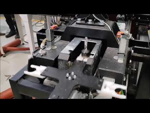
WORKING UNITS
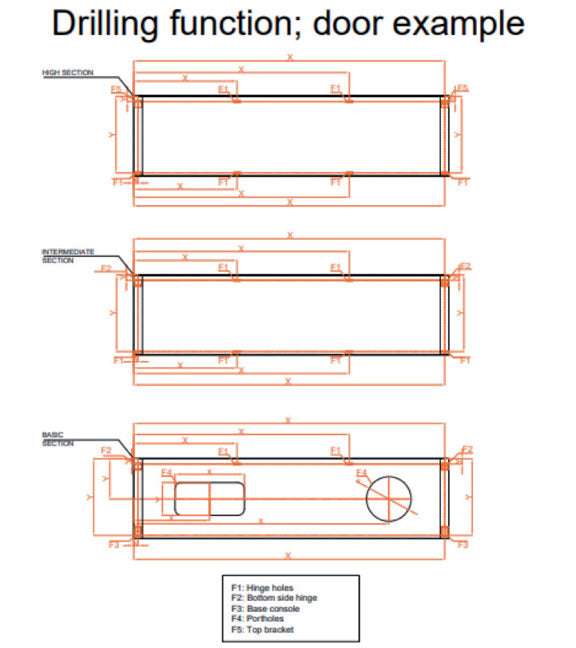
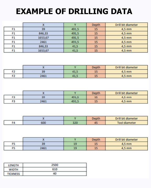
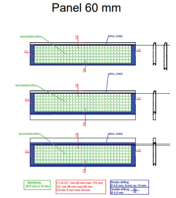
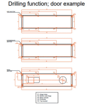
Working Unit Head with Two integrated Router Spindles
- Working unit for vertical drilling with independent spindles.
- Unit is mounted forward of the electrospindle giving complete table coverage
- Made in light aluminum alloy with high mechanical properties, the unit is equipped with:
- 4 spindles with vertical outlets 40 mm pitch from drill one to drill two and 45mm from drill two to drill three.
- Control of the spindles by an electro-valve and cylinder with single thrust chamber.
- The working unit is rotated by an asynchronous 1.7 kW (2.3 HP) electrical motor controlled by “inverter”.
- The motor, in turn, activates the transmission made of special steel gears with wide, slanting, rectified and thermally hardened teeth.
8 kW -S6 Electrospindle(10.7Hp – S6) 12,000 – 24000 RPM – ISO30
Mounted directly on the Z carriage, it slides on pre-loaded ball runner blocks and on two very high precision, hardened and rectified steel linear guides which guarantee an equal loading capacity in all 4 directions.
Maximum power 8 kW (10.7 Hp)
Rotation speed 12,000-24000 rpm
Driver three phase motor controlled by inverter
Rotation sense right and left
Spindle lubrication permanent greasing
Tool attachment ISO30 cone
5 kW -S6 Electrospindle(6.7Hp – S6) 12,000 – 24000 RPM – ISO30
Mounted directly on the Z carriage, it slides on pre-loaded ball runner blocks and on two very high precision, hardened and rectified steel linear guides which guarantee an equal loading capacity in all 4 directions.
Maximum power 5 kW (6.7 Hp)
Rotation speed 12,000-24000 rpm
Driver three phase motor controlled by inverter
Rotation sense right and left
Spindle lubrication permanent greasing
Tool attachment ISO30 cone
4 Position Linear tool Magazine for the 8Kw Spindle
Four (4) position rotary magazine with automatic change managed by CN
MACHINE CONTROL AND SOFTWARE
NUMERICAL CONTROL
The “TPA CAD” Numerical Control incorporates leading-edge, true PC-control on the Busellato, avoiding proprietary PLC control systems. Review major features below and see our website https://jklmachinery.us/products/tpa-genesis-evolution-training
for video tutorials on Genesis Evolution.
- CAD integrated in the control with mirroring, rotation, repetition functions, etc.
- “Multitasking” operating system for using the control even when the machine is working
- Graphical display of the 6 workable faces
- 2D and 3D display of the piece being worked
- Parametric programming which permits the use of mathematical, trigonometric, inverse trigonometric and logical formulas and the use of 300 variables.
- Programming on horizontal, vertical faces and virtual faces which can be rotated, very helpful for when using aggregates.
- Programming of linear, circular, oval and ellipse routings on the three Cartesian axes
- Programming of tool radius with automatic correction
- Possibility of excluding the display of some types of machining
- Multi-level zoom function
- Conditioned programming (IF/EndIF Blocks) associated with the use of Macros
- Absolute or incremental programming
- Creating of sub-programs by the operator with the possibility of multiplication, mirroring and rotation of the above
- Up to 10,000 program lines (expandable) are programmable
- Customer can personalize error messages
- Easy identification of stored programs using “preview” function
- Archiving of programs with names up to 256 characters long
- In line recall of the machine set-up and tool specifications
- Management of up to 500 tools
- Graphical display of set up of tool changers
- Tool graphical archive with the possibility of parameterizing up to 9000 different types of tools
- Pocket cycle in defined planes
- Pocket cycle with three modes- Simple pocket, relief and reverse relief
- Programming of all TRUE TYPE ANSI fonts installed in PC (up to 255)
- Linear or curved text orientation
- Management of distances between characters, height, size, bold, italics
- Built-in oscilloscope capable of monitoring the logical input/output status and the dynamic axes’ parameters
- Visualization of the rpm and absorbed current of the aggregates and spindle
- Importation or files from previous Busellato CNC versions (Genesis, Winner90, CNC 90)
- Bar code reading software
- Calculation of time required for program execution
- Program simulation of working cycle
- Manual and machine diagnostic functions in real time with graphic help
- Management and diagnostic synoptics which makes using the machine easier
- Program list management and variable control from the list
- Automatic control of the working speed to optimize the routing path.
TRAINING
The entire installation and on-site training process will be completed within 32 labor hours, unless otherwise agreed in writing. Our technicians use a comprehensive checklist to commission the machine and train your operators on the operation. Some of the topics covered:
- Machine safety and operation
- Lubrication procedures and maintenance schedule
- Tooling installation and parameters
- Review of electrical, parts and instruction manuals
- Control cabinet layout and major electrical components
- Processing of your programmed parts


